
Anyone can buy a roller or a plate compactor. The harder question on every site is this: how does the engineer prove that the soil has actually reached the required compaction?
The answer is the Field Density Test (FDT). It is the quality-control check that turns “the roller made enough passes” into a number you can put in a test report and defend to a client.
This guide explains what FDT is, how the main methods work under Indian standards, how to calculate the degree of compaction with a worked example, and what to do when a test fails.
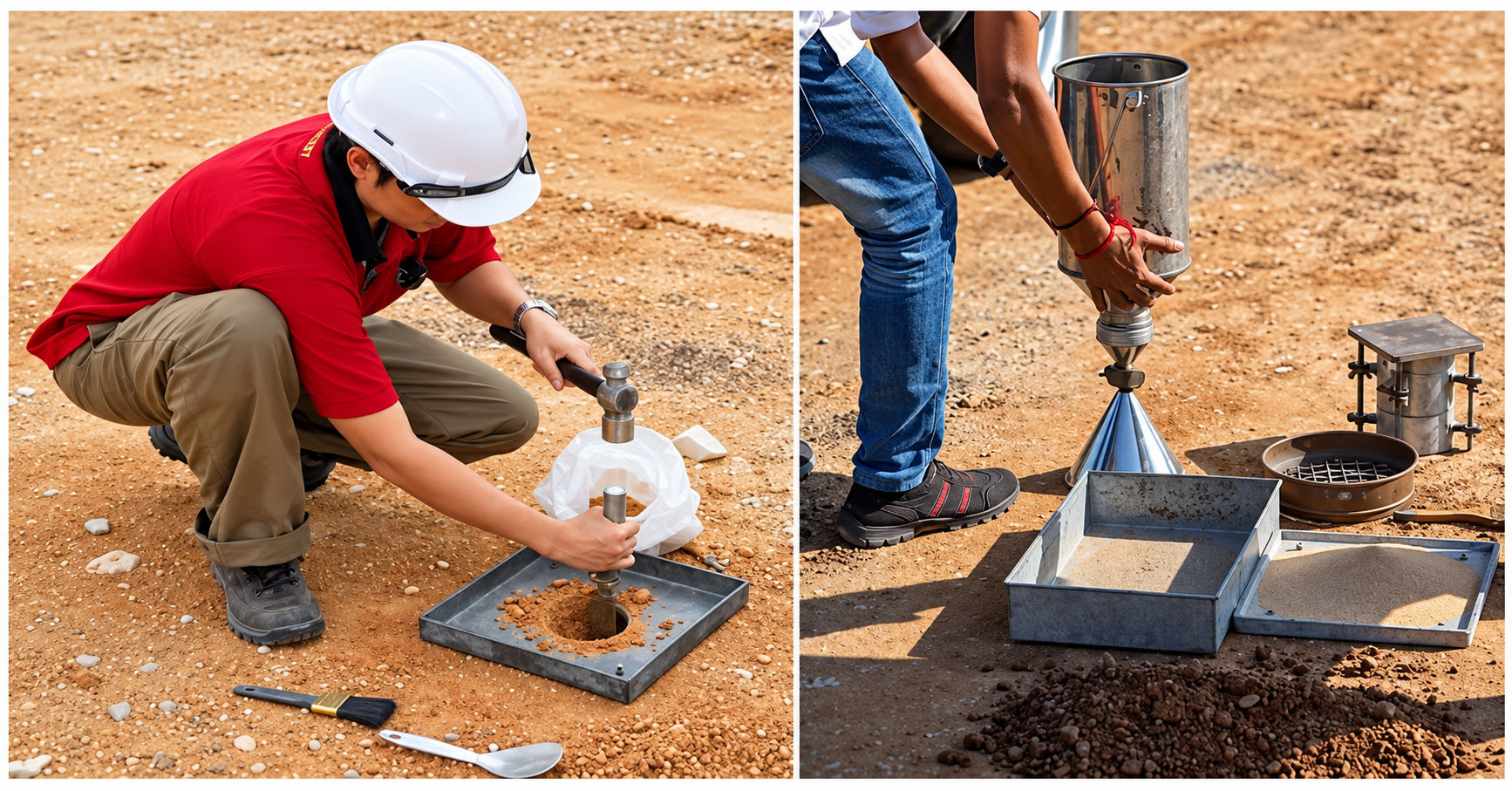
A Field Density Test measures the in-place dry density of compacted soil or granular material at a specific location and layer. That field value is then compared with the maximum dry density (MDD) obtained in the laboratory for the same material. The ratio, expressed as a percentage, is the degree of compaction.
In short, the laboratory tells you what density the soil can achieve. The FDT tells you what density the site actually achieved.
Compaction is invisible once the next layer is placed. A poorly compacted layer can look perfectly fine on the surface and still cause problems months later. FDT matters because it:
Before interpreting any field result, you need two laboratory values for the soil being compacted.
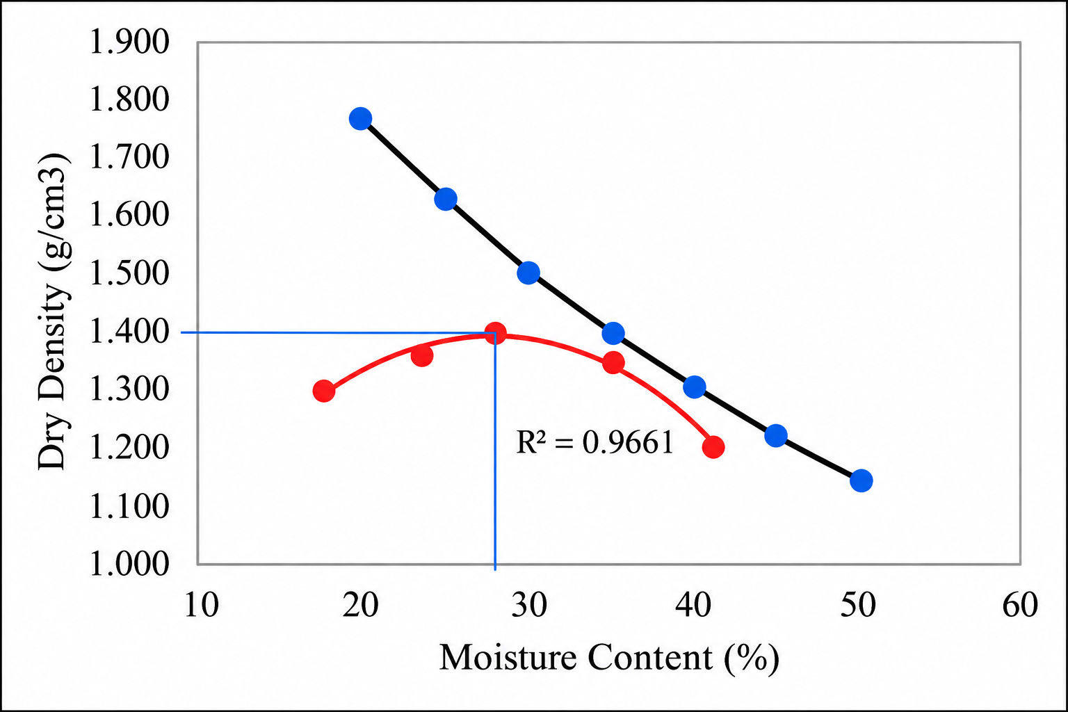
Maximum Dry Density (MDD) is the highest dry density the soil reaches under a standard compactive effort in the laboratory.
Optimum Moisture Content (OMC) is the water content at which that maximum density is achieved.
Both come from the Proctor compaction test. For heavy compaction (modified Proctor), the Indian standard is IS 2720 (Part 8). Soil is compacted in a mould at several different moisture contents, the dry density is calculated for each, and the results are plotted as a compaction curve. The peak of that curve gives MDD, and the moisture content at the peak gives OMC.
Three methods are widely used on Indian sites. Two are covered directly by IS 2720 and one is an instrument-based method.
| Method | Standard | Best suited for | Main limitation |
|---|---|---|---|
| Sand Replacement | IS 2720 (Part 28) | Fine-grained and granular soils, layers with some gravel | Slower; sensitive to vibration; sand must be dry and calibrated |
| Core Cutter | IS 2720 (Part 29) | Soft to medium cohesive, fine-grained soils with little or no gravel | Not suitable for stony, gravelly or very hard soils; limited depth |
| Nuclear Density Gauge | ASTM D6938 (international) | Large projects needing many fast, non-destructive tests | Needs licensed operators and radiation-safety handling; calibrated against sand replacement |
Covered by IS 2720 (Part 28), this is the most commonly specified method for fine-grained and granular soils, and for layers containing some gravel.
Principle: a small hole is excavated in the compacted layer and the soil removed is weighed. The volume of the hole is found by filling it with calibrated, uniform sand of known bulk density.
Equipment:
Best suited for: most embankment, subgrade and sub-base layers, and materials where a core cutter cannot be driven in.
Limitations: it is slower than other methods, results are sensitive to vibration near the test point, and the sand must be kept dry and calibrated.
Covered by IS 2720 (Part 29), this method uses a steel cylinder of known volume that is driven into the soil.
Principle: the cutter is driven into the compacted layer, dug out with the soil intact inside it, trimmed flush and weighed. Because the volume is already known, density follows directly.
Equipment: core cutter (commonly 100 mm diameter and 130 mm height), dolly, rammer, straight edge, balance and moisture cans.
Best suited for: soft to medium cohesive, fine-grained soils with little or no gravel.
Limitations: not suitable for stony, gravelly or very hard soils, because the cutter cannot be driven in without disturbing the sample. It also tests a limited depth only.
A nuclear density gauge estimates density and moisture by measuring radiation transmitted through or scattered back from the soil. It is commonly specified internationally under ASTM D6938 and is used on some large projects.
Advantages: very fast, non-destructive and allows many tests in a short time.
Limitations: it needs licensed operators and strict radiation-safety handling, and it is usually calibrated against sand replacement results. Many Indian specifications still treat sand replacement as the referee method, so confirm what your contract accepts.
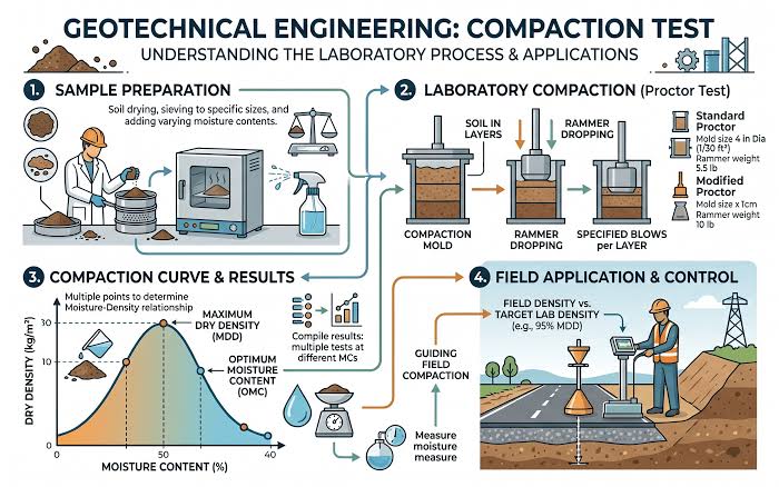
The steps below describe the sand replacement method, the one most engineers are asked to perform.
Here is a worked sand replacement example using realistic figures.
Given:
| Parameter | Value |
|---|---|
| Mass of cylinder with sand before test | 7,500 g |
| Mass of cylinder with sand after test | 4,060 g |
| Mass of sand in the cone (from calibration) | 1,280 g |
| Bulk density of calibrated sand | 1.50 g/cc |
| Mass of wet soil excavated from the hole | 2,950 g |
| Field moisture content | 11 % |
| Laboratory MDD (heavy compaction, IS 2720 Part 8) | 1.90 g/cc |
| Laboratory OMC | 12 % |
Calculation:
| Step | Description | Calculation | Result |
|---|---|---|---|
| 1 | Sand used in the test | 7,500 − 4,060 | 3,440 g |
| 2 | Sand filling the hole alone | 3,440 − 1,280 | 2,160 g |
| 3 | Volume of the hole | 2,160 ÷ 1.50 | 1,440 cc |
| 4 | Wet (bulk) density of the soil | 2,950 ÷ 1,440 | 2.049 g/cc |
| 5 | Dry density of the soil | 2.049 ÷ 1.11 | 1.846 g/cc |
Dry density = Wet density ÷ (1 + w), where w is moisture content as a decimal.
Result: the field dry density is about 1.85 g/cc.
The degree of compaction compares field density with the laboratory benchmark:
Degree of Compaction (%) = (Field Dry Density ÷ Laboratory MDD) × 100
Using the example above:
1.846 ÷ 1.90 × 100 = 97.1 %
That layer achieves 97.1 % of the laboratory MDD. Whether this passes depends on the specification. If the requirement for that layer is 97 %, it passes narrowly. If it is 98 %, it fails and the layer needs further compaction.
There is no single universal acceptance percentage. The required degree of compaction depends on:
Many road and infrastructure specifications call for a high percentage of heavy-compaction MDD on subgrade and upper layers, with a slightly lower figure on lower embankment layers. Railway earthwork guidelines separately define their own testing frequencies and acceptance criteria.
The practical rule is simple: always read the project technical specification first, then confirm the required percentage, the testing frequency per area or volume, and the reference MDD standard before starting work.
When a test fails, the cause is usually one of the following:
| Cause | What happens |
|---|---|
| Wrong moisture content | Soil rolled too dry or too wet will not reach density, no matter how many passes are made. |
| Excessive lift thickness | Compaction energy fades with depth, so thick layers end up dense at the top and loose at the bottom. |
| Wrong or undersized equipment | A light machine on a heavy or cohesive soil will not deliver enough energy. |
| Insufficient passes | Too few passes, or uneven coverage leaving gaps between roller tracks. |
| Variable material | A change in soil type from the borrow area means the original MDD no longer applies. |
| Poor subgrade support | A soft layer underneath absorbs the compactive effort. |
| Wrong reference MDD | Comparing field results with an MDD from a different soil. |
| Testing errors | Lost soil during excavation, vibration during sand pouring, uncalibrated sand or inaccurate moisture determination. |
If results are falling short, work through this list:
The right machine depends on the soil, the layer and the working space. Here is how the main equipment types fit different site conditions.
Walk-behind rollers. Suited to small to medium areas, narrow roads, footpaths, service corridors and patch work where a large ride-on roller cannot operate. Explore Walk Behind Rollers for options.
Ride-on rollers. The practical choice for larger areas such as highway embankments, subgrade and sub-base layers, where productivity and consistent coverage matter most. See Ride on Rollers for the range.
Plate compactors. Best for granular and semi-granular soils in confined areas, around structures, pavers and small trenches. See Plate Compactors for the range.
Tamping rammers. Ideal for cohesive and mixed soils in trenches, foundation pits, around columns and in other restricted spaces where plates cannot reach. Browse Tamping Rammers for suitable models.
Which IS codes cover the field density test?
IS 2720 (Part 28) covers the sand replacement method and IS 2720 (Part 29) covers the core cutter method. IS 2720 (Part 8) covers the laboratory moisture–dry density relationship using heavy compaction.
How do you calculate the degree of compaction?
Divide the field dry density by the laboratory MDD and multiply by 100.
What percentage of compaction is required?
It depends on the project specification, layer type and contract. Always follow the technical specification for your project.
Which method is better, sand replacement or core cutter?
Sand replacement works for a wider range of soils, including gravelly ones. Core cutter is quicker but suited only to soft, fine-grained cohesive soils.
Can a nuclear density gauge replace sand replacement?
It can speed up testing, but many specifications still require sand replacement as the reference or calibration method. Confirm with your client’s requirements.
Field Density Test (FDT): Methods, Procedure & Calculation

India’s Infrastructure Push Is Driving Demand for Construction Machinery, but the Ground Reality Is More Complex

Soil vs Asphalt Compaction: 7 Practical Differences Every Site Engineer Should Know

Smarter Machines, Stronger Roads: How Mechanisation Is Rebuilding India’s Road Construction

₹12.2 Lakh Crore for Infrastructure: Which Construction Machines Will Be in Demand?

Copyright © 2026 Sona Construction Technologies Private Limited